What is a bootloader, and what is bootloading?
The bootloader is the little program that runs when you turn the Arduino on, or press the reset button. Its main function is to wait for the Arduino software on your computer to send it a new program for the Arduino, which it then writes to the memory on the Arduino. This is important, because normally you need a special device to program the Arduino. The bootloader is what enables you to program the Arduino using just the USB cable.
When we refer to "bootloading" the Arduino, we are talking about using a special device (called an In-System Programmer or ISP) to replace the bootloader software.
Normally the default bootloader of arduino is Optiboot
Here I am showing that an alternative and some more advanced options in Arduino bootloader option called MiniCore
Why MiniCore?
An Arduino core for the ATmega328, ATmega168, ATmega88, ATmega48 and ATmega8, all running a custom version of Optiboot for increased functionality.
- Bootloader option
- BOD option
- Link time optimization / LTO
- Printf support
- Pin macros
- Programmers
- Write to own flash
Bootloader option
MiniCore lets you select which serial port you want to use for uploading. UART0 is the default port for all targets, but ATmega328PB can also use UART1. If your application doesn't need or require a bootloader for uploading code you can also choose to disable this by selecting No bootloader. This frees 512 bytes of flash memory.
Note that you need to connect to a programmer and hit Burn bootloader if you want to change any of the Upload port settings.
BOD option
Brown out detection, or BOD for short lets the microcontroller sense the input voltage and shut down if the voltage goes below the brown out setting. To change the BOD settings you'll have to connect an ISP programmer and hit "Burn bootloader". Below is a table that shows the available BOD options:

Printf support
Unlike the official Arduino cores, MiniCore has printf support out of the box. If you're not familiar with printf you should probably read this first. It's added to the Print class and will work with all libraries that inherit Print. Printf is a standard C function that lets you format text much easier than using Arduino's built-in print and println. Note that this implementation of printf will NOT print floats or doubles. This is a limitation of the avr-libc printf implementation on AVR microcontrollers, and nothing I can easily fix.
If you're using a serial port, simply use Serial.printf("Milliseconds since start: %ld\n", millis());. Other libraries that inherit the Print class (and thus supports printf) are the LiquidCrystal LCD library and the U8G2 graphical LCD library.
Pin macros
Note that you don't have to use the digital pin numbers to refer to the pins. You can also use some predefined macros that maps "Arduino pins" to the port and port number:
// Use PIN_PB5 macro to refer to pin PB5 (Arduino pin 13)
digitalWrite(PIN_PB5, HIGH);
// Results in the exact same compiled codedigitalWrite(13, HIGH);
Programmers
MiniCore does not add its own copies of all the standard programmers to the "Programmer" menu. Just select one of the stock programmers in the "Programmers" menu, and you're ready to "Burn Bootloader" or "Upload Using Programmer".
Select your microcontroller in the boards menu, then select the clock frequency. You'll have to hit "Burn bootloader" in order to set the correct fuses and upload the correct bootloader.
Make sure you connect an ISP programmer, and select the correct one in the "Programmers" menu. For time critical operations an external oscillator is recommended.
Write to own flash
MiniCore implements majekw fork of Optiboot, which enables flash writing functionality within the running application. This means that content from e.g. a sensor can be stored in the flash memory directly, without the need of external memory. Flash memory is much faster than EEPROM, and can handle about 10 000 write cycles.
To enable this feature your original bootloader needs to be replaced by the new one. Simply hit "Burn Bootloader", and it's done!
Check out the Optiboot flasher example for more info about how this feature works, and how you can try it on your MiniCore compatible microcontroller.
ATMEGA* Memory & PWM Pins table
* ATmega328PB has 9 PWM pins
Supported clock frequencies
Boards Manager Installation
- This installation method requires Arduino IDE version 1.6.4 or greater.
- Open the Arduino IDE.
- Open the File > Preferences menu item.
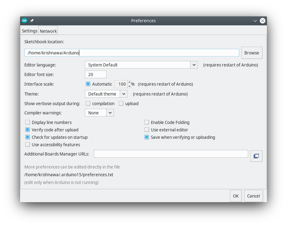
- Enter the following URL in Additional Boards Manager URLs
https://mcudude.github.io/MiniCore/package_MCUdude_MiniCore_index.json- Open the Tools > Board > Boards Manager... menu item.
- Wait for the platform indexes to finish downloading.
- Scroll down until you see the MiniCore entry and click on it.

- After installation is complete close the Boards Manager window.
- Note: If you plan to use the *PB series, you need the latest version of the Arduino tool chain. This tool chain is available through IDE 1.8.6 or newer. Here's how you install/enable the tool chain:
- Open the Tools > Board > Boards Manager... menu item.
- Wait for the platform indexes to finish downloading.
- The top is named Arduino AVR boards. Click on this item.
- Make sure the latest version is installed and selected
- Close the Boards Manager window.
- Click Install.
Manual Installation
- Click on the "Download ZIP" button in the upper right corner. Extract the ZIP file, and move the extracted folder to the location "~/Documents/Arduino/hardware". Create the "hardware" folder if it doesn't exist. Open Arduino IDE, and a new category in the boards menu called "MiniCore" will show up.
Wiring

Comments
Post a Comment