
BEE WATCH MK1

Introduction

I am very interested in making small gadgets so this is my first attempt to working on a simple OLED watch, I was inspired from N|Watch project, My version is arduino compatible.The main component of this watch is it’s RTC, The RTC IC used here ISL1208 and my friend Vishnu M Aiea is developed the arduino library for ISL1208, If you are interested in that please take a look to his documentation about ISL1208 .


Specification

  • 1.3” OLED Display
  • ATMEGA328P Microcontroller
  • Alarm feature
  • Timer
  • BPM Sensor
  • Temperature Sensor
  • Game

HARDWARE

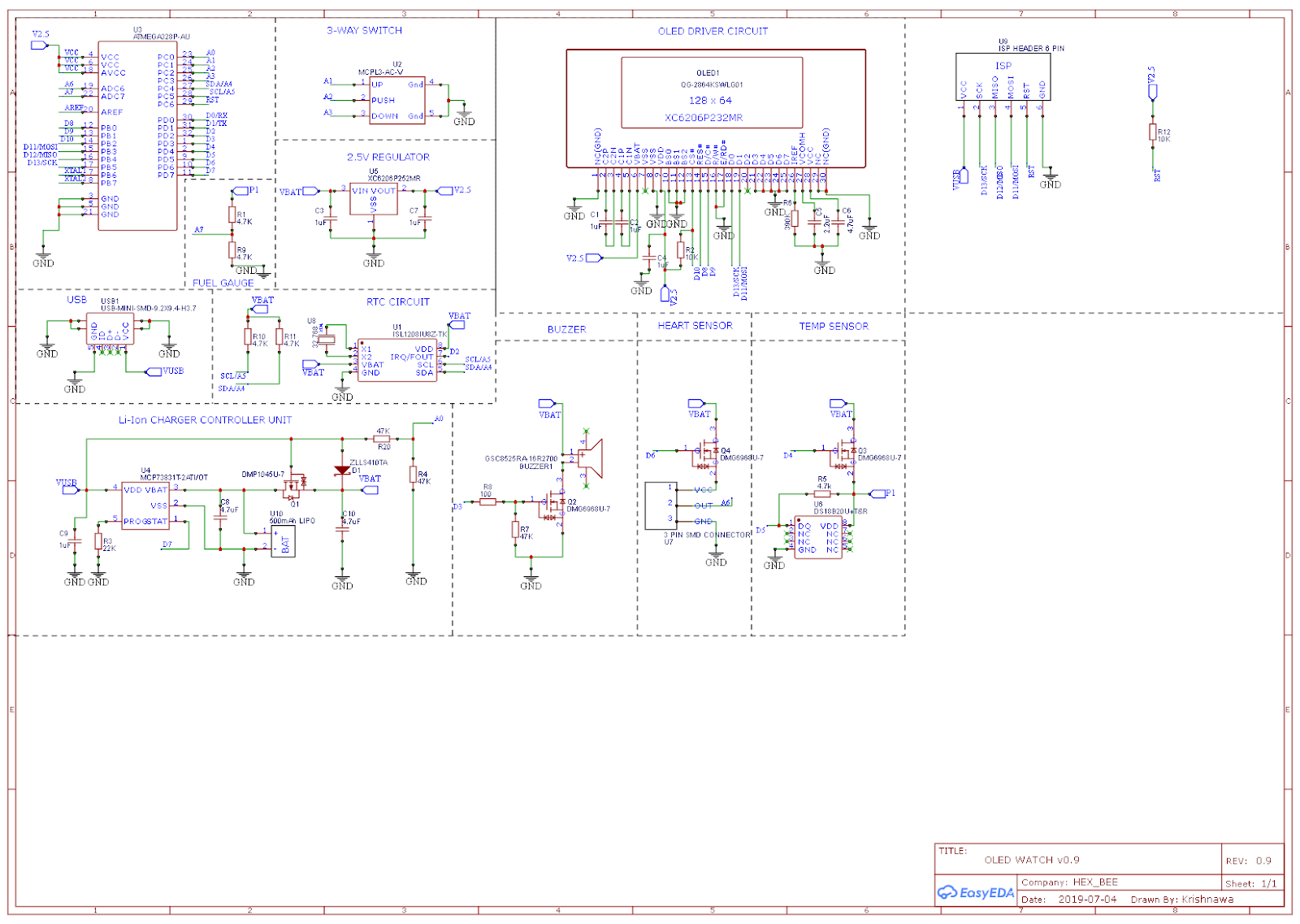
BEE WATCH MK I SCHEMATIC
On the hardware side the watch contains an Atmel ATmega328P microcontroller, 2.5V regulator, ISL1208 RTC IC from Intersil RTC, 1.3″ 128×64 monochrome OLED, Heart sensor, a buzzer sounder, 3 way switch for navigation, powered by a 150mAh LiPo battery which can be charged via Mini USB

The ATmega328P uses its internal 1MHz oscillator and runs on 2.5V from a linear regulator. Its current draw is around 1.5mA when active and 100nA in sleep mode.Here I used MiniCore instead of Optiboot

The Intersil ISL1208 is a low power RTC chip with I2C interface. It uses an external 32.768KHz crystal to keep track of the time and has month-date-hour-min-sec alarm registers. It only consumes around 400nA in battery (VBAT) operation and a maximum of 1.2uA on external supply voltage (VDD). The operating voltage is from 1.8V to 5.5V. What makes this a good candidate are the low power consumption and the month-date alarm feature. Normal RTCs such as DS1307 do not have a month setting in alarm register.

The battery charging circuit uses a Microchip MCP73832 along with some additional components for load sharing, where the battery can charge without the rest of the watch interfering with it.

As the microcontroller is running on 2.5V the battery voltage needs to be brought down a bit to obtain an ADC reading. This is done by a simple voltage divider. However, with the voltage divider connected across the battery there would be a current of around 350uA constantly flowing through it, this is a huge waste of power. A P-MOSFET (and some voltage level conversion for it, which I forgot about in the first version so it was always stuck on) was added so the divider can be turned on only when needed.

The 2.5V regulator being used is a Torex XC6206, primarily chosen for its tiny quiescent current of just 1uA.

Why a linear regulator and not a switching regulator? The switching regulators I looked at had an efficiency of at least 80% with a 2mA load, but that efficiency quickly dropped off to less than 50% with loads of 100uA. Since the devices connected to the regulator draw 2-3uA in sleep mode, a switching regulator would have performed incredibly poor compared to a linear regulator. The 2.5V linear regulator efficiency is 60% with 4.2V input going up to 83% with 3V input.

Comments

Popular posts from this blog

ATMEGA328P-TQFP32-PINOUT

Here'a a pinout diagram I created for the ATMEGA328P TQFP32 . It is shared under CC-BY-SA license. You're free to modify it and share. Just give a backlink to my project website if possible (I have not posted the pinout diagram on my website yet. I'm also attaching a PDF,SVG version so that you can edit with any vector editing software. If you want me to create pinout diagrams for other boards, I'd be happy spend some free time on it. Let me know. Hope you'll find it useful :)  Github: https://github.com/Krishnawa/ATMEGA328P-TQFP32-PINOUT

Arduino-Register Programming

Simple LED Blink Program Here I'm explained my first register level coding, It is awesome and it's make me much more understand about how the microcontroller is working, I'm still learning, so here I'm sharing what I understood. Are you ready for this then let's go Arduino language Blink program This is simple Blink program without using any functions!. Take a look at the code the same code is converting to register level unsigned long counter = 0 ; // initializing  counter variable and set to 0 void setup ( ) {   pinMode ( LED_BUILTIN , OUTPUT ) ; // set 13th pin LED as output   Serial . begin ( 9600 ) ; // initializing Serial communications } void loop ( ) {   counter ++ ; //increment the counter   Serial . println ( counter ) ; // print the counter value on Serial monitor   if ( counter > 250 ) {     digitalWrite ( LED_BUILTIN , HIGH ) ; // if counter value greater than 250 then LED turn ON   }   if ( counter > 5

Bootloader - Arduino

What is a bootloader, and what is bootloading? The bootloader is the little program that runs when you turn the Arduino on, or press the reset button. Its main function is to wait for the Arduino software on your computer to send it a new program for the Arduino, which it then writes to the memory on the Arduino. This is important, because normally you need a special device to program the Arduino. The bootloader is what enables you to program the Arduino using just the USB cable. When we refer to "bootloading" the Arduino, we are talking about using a special device (called an In-System Programmer or ISP) to replace the bootloader software. Normally the default bootloader of arduino is Optiboot Here I am showing that an alternative and some more advanced options in Arduino bootloader option called MiniCore Why MiniCore? An Arduino core for the ATmega328, ATmega168, ATmega88, ATmega48 and ATmega8, all running a custom version of Optiboot for increased functio